24V DRIVEN MOTOR ROLLERS
24v Motor Driven Rollers can be used in a number of applications. The most obvious is to be used in Roller Conveyor. The benefits with using 24v Driven Rollers are:-
NDW now offer the 'complete' Roller Package to Conveyor Manufacturers, with our Power Roller Range complimenting our established Slave Roller production.
- Reduced Electricity Consumption
- Reduced Noise Level
- Flexible Systems
- Reduced Cost
- Run on Demand
- Product Accumulation without Product Contact
- Simplified Electrical Control System
- Enhanced Diagnostic
- Conveyor Up-time
- Reduced Time for Repair
NDW now offer the 'complete' Roller Package to Conveyor Manufacturers, with our Power Roller Range complimenting our established Slave Roller production.
BP120 Controller
Product description
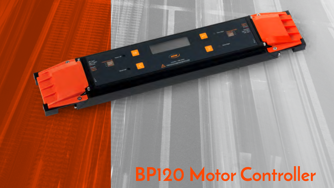
The BP120 controller is designed to drive two NDW motorized E-rollers. The BP120 has two integrated sensor connections and is suitable for a large range of intralogistics applications.
BP120 controllers can work together to create a system that is able to
work completely independent. With point-to-point communication and the integrated logic of the controller the need for an external control computer or PLC has disappeared. Furthermore, by adjusting the control parameters the system becomes very flexible to use.
No external power supply needed
Thanks to its integrated transformer the BP120 controller can immediately be connected to mains (110-230V) and is therefore the ultimate plug and play solution.
User friendly interface
The BP120 controller has a user-friendly interface, which makes it easy to change the settings on the controller. A graphical user interface (UI) and straightforward buttons can be used to change the settings. As a result, no DIP switches are required on this controller. In this user manual all the different settings are explained.
Plug and Play
The BP120 controllers have preprogrammed settings for simple installation and testing. Furtermore, every BP120 controller can communicate with the controller to its left and right. This makes it possible to expand the system in an accumulating way and it is possible to integrate more complex tasks. For example, this enables fully autonomous Zero Pressure Accumulation (ZPA) modes. On top of that, using the integrated logic of the controllers, everything can be completely customized. Gathering packages, synchronized modes, adjusting delays and so much more can be set using the controllers.
Simple control using I/O
The BP120 controller also offers simple control using the I/O connections. These can be controlled using an external source (24V PNP or NPN). Settings such as direction and speed can be easily adjusted using these settings. Within the Settings-section page 24 you can find how to adjust these settings.
Key Functions
Zero Line Pressure Accumulation
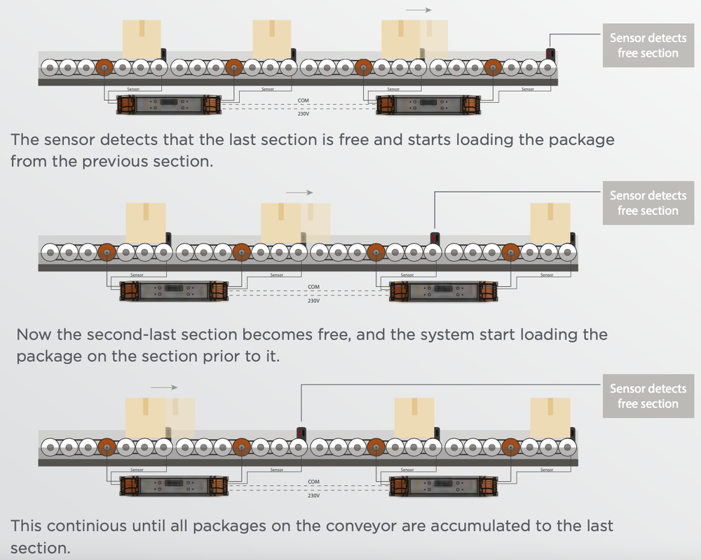
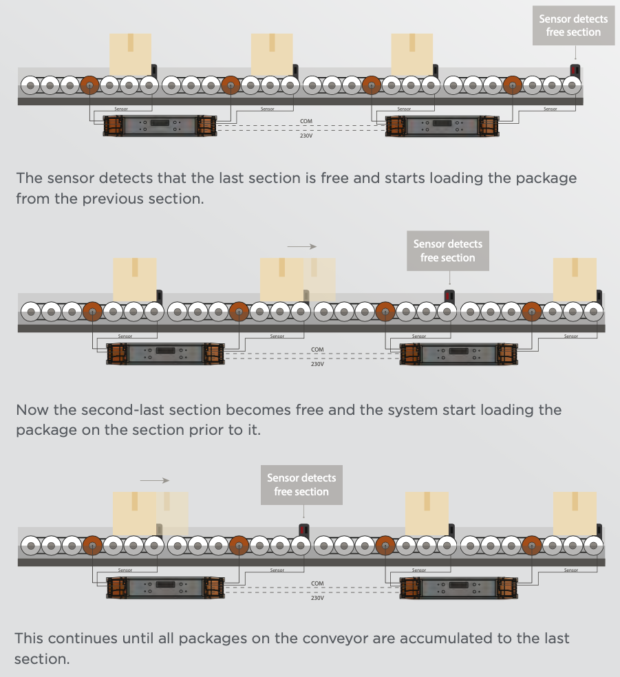
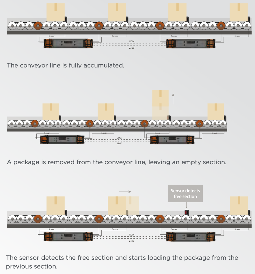
The BP120 controllers can provide fully autonomous Zero Pressure Accumulation (ZPA) applications. This allows for transportation of goods without them coming into contact with each other. The conveyor system is divided in segments, with each segment having a sensor, a motorized E-roller and several slave rollers. Since the controllers are directly communicating with each other they know which segments have packages, which segments are loading packages and which are dispatching packages.
The BP120 controllers can provide fully autonomous Zero Pressure Accumulation (ZPA) applications. This allows for transportation of goods without them coming into contact with each other. The conveyor system is divided in segments, with each segment having a sensor, a motorized E-roller and several slave rollers. Since the controllers are directly communicating with each other they know which segments have packages, which segments are loading packages and which are dispatching packages.
Delay & Time-outs
The controller has multiple delays and time-outs which can be customized with ease. Such as dispatch-, load- and sensor delays. The customization of these delays makes it possible to make the system run as smooth as possible. All these settings and functions are explained in this user manual.
Forward mode
With multiple controllers chained together, it is possible to have all controllers and corresponding motors behave equally. This is particularly useful for long and simple conveyor systems. In this setup, it is only required to control a single BP120 controller, the rest will simply follow its behavior.
Stall protection
When the rotation of the motor is blocked, the controller will initiate a stall protection to protect the motor. The controller will try to resolve the stalled motor for a number of times. When the motor remains stalled, the controller will display an error on the screen and send an I/O error signal.
Overvoltage protection
The BP120 controller is equipped with a protection against induced overvoltage of the motorized E-roller when it acts as a generator.
Accumulation settings (ACC)
Within the accumulation settings one can find all the settings regarding accumulation. These settings include: Accumulation Enabling, Accumulation Direction, Smooth Function, Load Delays and Dispatch Delays. These settings are needed to make accumulation possible and to optimize the accumulation process. On the following pages the functionalities of these settings will be explained.
Accumulation
The accumulation function defines whether accumulation is enabled or disabled. This can be done by setting the function to ON or OFF. By enabling the accumulation function, it is possible to automate the whole conveyor system by letting the packages move downstream whenever there is an open spot to fill. The other functions in this menu make it possible to customize and optimize this process.
Endpoint
If the application requires external interaction with autonomously accumulating controllers, this can be done through the first or last controller in the ZPA chain. The external interaction takes places via I/O signals. The user can select ZPA- First, ZPA-Last or No (Default) as endpoint. When external interaction is desired, set the first controller in the ZPA chain to ZPA-First and the last controller to ZPA-last.
If the application requires external interaction with autonomously accumulating controllers, this can be done through the first or last controller in the ZPA chain. The external interaction takes places via I/O signals. The user can select ZPA- First, ZPA-Last or No (Default) as endpoint. When external interaction is desired, set the first controller in the ZPA chain to ZPA-First and the last controller to ZPA-last.
Direction
The Accumulation Direction setting lets the system know in what direction
the accumulation is going (viewed from the front of the controller). By communicating this to the whole system it knows from which side it will receive or which side it as to dispatch the packages. Note that this setting has no relation to the turning direction of the E-roller.
Smooth function
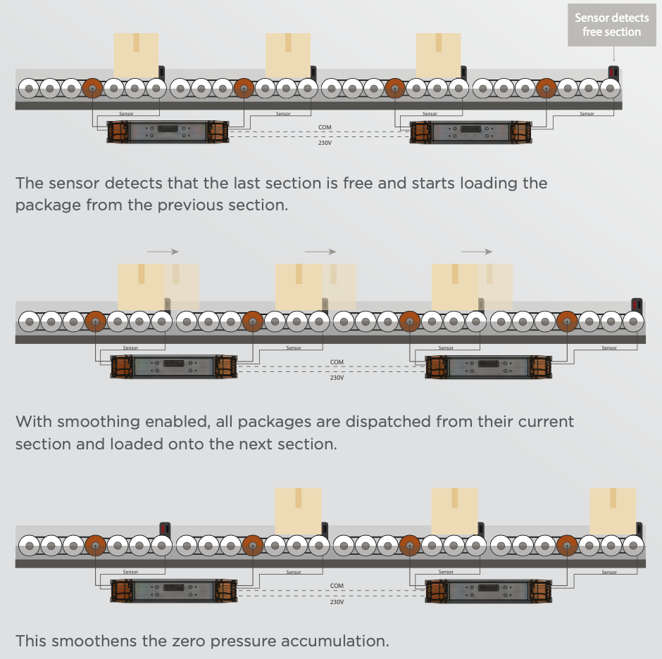
The accumulation Smooth Function has two different sub functions, Enabled and Delay. The Enable function will enable the system to transport multiple packages at the same time. When disabled, the conveyor belt will transport the packages one by one. When smoothing is enabled it is also possible to define a small delay for optimization purposes. In most cases, it is not recommended to enable this function since it could increase the chances of errors during accumulation. Only use this setting when transport times are very critical.
The Accumulation Direction setting lets the system know in what direction
the accumulation is going (viewed from the front of the controller). By communicating this to the whole system it knows from which side it will receive or which side it as to dispatch the packages. Note that this setting has no relation to the turning direction of the E-roller.
Smooth function
The accumulation Smooth Function has two different sub functions, Enabled and Delay. The Enable function will enable the system to transport multiple packages at the same time. When disabled, the conveyor belt will transport the packages one by one. When smoothing is enabled it is also possible to define a small delay for optimization purposes. In most cases, it is not recommended to enable this function since it could increase the chances of errors during accumulation. Only use this setting when transport times are very critical.
NumToCollect
The NumToCollect function can be set in order to define how many packages will be collected on each segment of the conveyor belt system. As default, NumToCollect is set to 1. If this value is set to 2 for a segment, the controller will wait until it has collected two packages on the segment before it is transported to the next segment.
RunIfEmpty
The RunIfEmpty function defines whether the conveyor belt will run or not when it is empty. This can be set by setting the function function to YES or No.
By enabling the run if empty function the segment will run even though the system does not detect a package. This function can be very useful for the
first segment in a chain of accumulating controllers. With RunIfEmpty on, the segment is always ready to receive an incoming package.
Sensor
Load delays
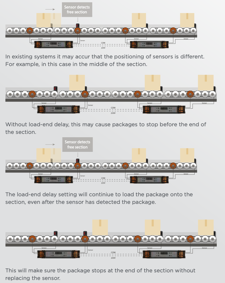
The sensor detects that the last section is free and starts
The accumulation load dleolaadyingfuthnecptaicoknagehfarosmththreeperesviuobus fseucnticontions: Start Delay, End
Delay and Time-out Delay.
Load start delay
The Load Start Delay makes it possible to decrease the distance between the packages sometimes created while transporting them. By creating a delay before the segment starts loading the package. This is mostly used in combination with the NumToCollect function.
Min. value: 0 sec, max. value: 2 sec, stepsize: 50 ms
Load end delay
In some cases the sensor might not be placed at the end of the segment. This would normally cause the segment to collect the boxes somewhere in the middle instead of the end. By using the Load End Delay it is possible to create a delay for which time the segment should keep running even after a package has been detected. This makes it possible to collect package at the end, even when the sensor is not placed at the ideal situation. Make sure the sensor still detects some part of the package, otherwise the controller thinks the conveyor segment is empty.
Min. value: 0 sec, max. value: 3 sec, stepsize: 50 ms
The NumToCollect function can be set in order to define how many packages will be collected on each segment of the conveyor belt system. As default, NumToCollect is set to 1. If this value is set to 2 for a segment, the controller will wait until it has collected two packages on the segment before it is transported to the next segment.
RunIfEmpty
The RunIfEmpty function defines whether the conveyor belt will run or not when it is empty. This can be set by setting the function function to YES or No.
By enabling the run if empty function the segment will run even though the system does not detect a package. This function can be very useful for the
first segment in a chain of accumulating controllers. With RunIfEmpty on, the segment is always ready to receive an incoming package.
Sensor
Load delays
The sensor detects that the last section is free and starts
The accumulation load dleolaadyingfuthnecptaicoknagehfarosmththreeperesviuobus fseucnticontions: Start Delay, End
Delay and Time-out Delay.
Load start delay
The Load Start Delay makes it possible to decrease the distance between the packages sometimes created while transporting them. By creating a delay before the segment starts loading the package. This is mostly used in combination with the NumToCollect function.
Min. value: 0 sec, max. value: 2 sec, stepsize: 50 ms
Load end delay
In some cases the sensor might not be placed at the end of the segment. This would normally cause the segment to collect the boxes somewhere in the middle instead of the end. By using the Load End Delay it is possible to create a delay for which time the segment should keep running even after a package has been detected. This makes it possible to collect package at the end, even when the sensor is not placed at the ideal situation. Make sure the sensor still detects some part of the package, otherwise the controller thinks the conveyor segment is empty.
Min. value: 0 sec, max. value: 3 sec, stepsize: 50 ms
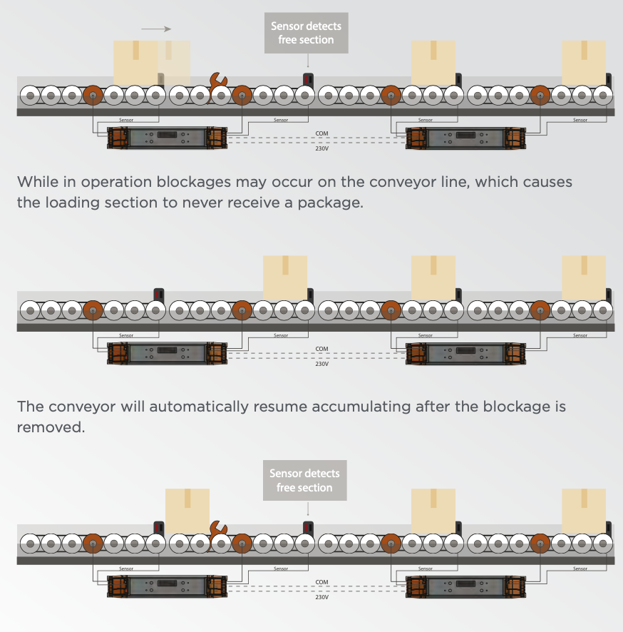
Load time-out delay
To make sure the motors will not keep running the moment a package is blocked, the Load Time-Out Delay function is used. The specified time-out delay is the time for which a segment will attempt to load a package. If this package does not arrive within this time, the controller will stop the motor and send an error to the controller. Which is visible on the screen of the controller, it will light up and clearly show an error message. The system will try to resolve the error by retrying to load a package after a certain time.
Min. value: 5 sec, max. value: 30 sec, stepsize: 1 s
|
The section attempts to load the package until the specified load timeout delay. After the loadtimeout delay, the section stops loading and sends an error message to the controller.
|
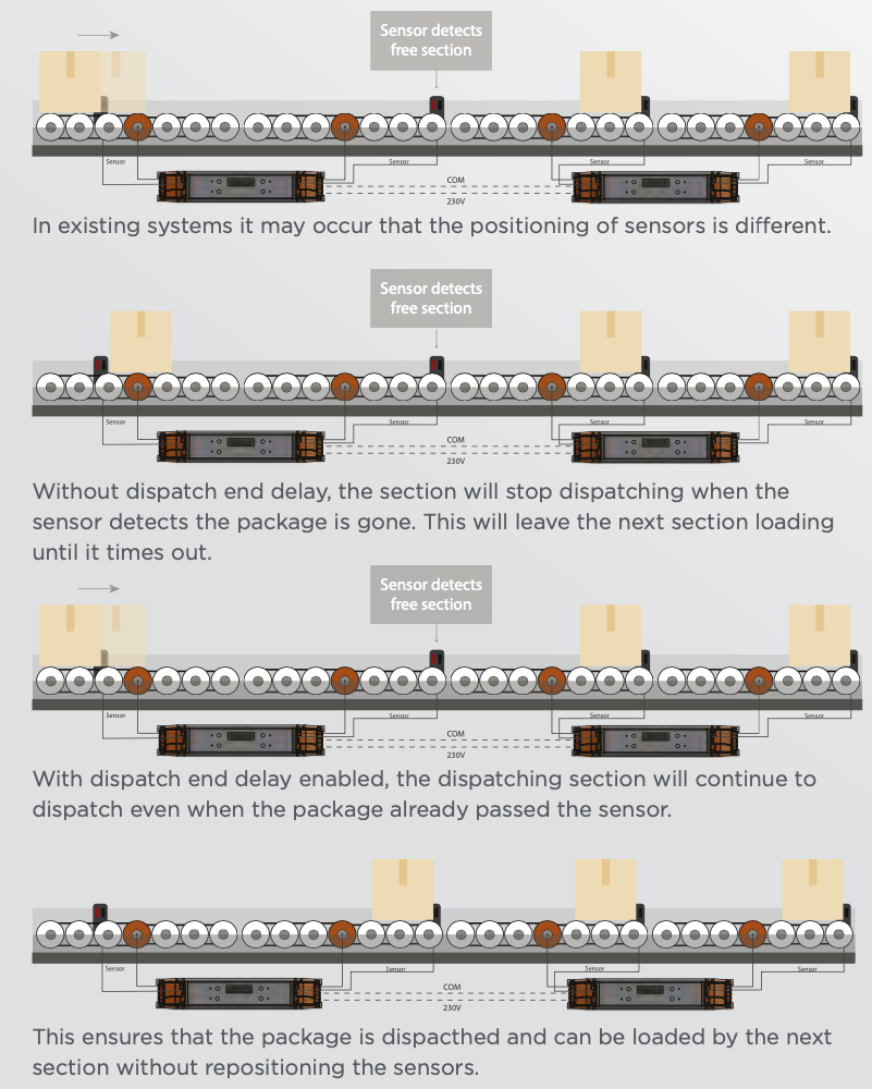
Dispatch delays
The accumulation dispatch delay function has two sub-functions: End Delay and Time-Out Delay.
Dispatch end delay
In some cases the sensor might not be placed at the end of the segment. This might cause certain segments to think they have dispatched a package even though it is still on the segment but out of reach of the sensor. By using the Dispatch End Delay function it is possible to create a delay for which the segment should keep running after it stops detecting a package.
Min. value: 0 sec, max. value: 3 sec, stepsize: 50 ms
Dispatch time-out delay
To make sure the motors will not keep running the moment a sensor is blocked the Dispatch Timeout Delay function is used. The specified time-out delay is the time for which a segment will attempt to dispatch a package. If this package appears to have not dispatched within this time the controller will stop the motor and send an error signal to the controller. Which is visible on the screen of the controller, it will light up and clearly show an error message. After this time-out the system will retry to dispatch the package every 10 seconds, to see if the error has been fixed.
Min. value: 5 sec, max. value: 30 sec, stepsize: 1 s
Interaction with ZPA system
In many applications it is desirable to interact with the autonomously accumulating BP120 controllers. For example, if one would like to transport a product to the first segment of the ZPA chain, you must be able to communicate to this segment to start loading a product. Whereas, for the last segment in the ZPA chain, you would like to control when this segment dispatches a product downstream.
Configuration of settings in BP120
It is possible to interact and communicate with the first and last segment of the ZPA chain via external I/O. To communicate via I/O with the first and/or last segment, two settings in the UI must be set:
(1) the first and/or last segment must be set to I/O-mode. (Make sure only one side of the BP120 controller is set to I/O-mode since the other side of the controller is still communicating with the rest of the ZPA chain in COM-mode).
(2) Endpoint setting must be set to ZPA-first for the first segment and ZPA-last for the last segment. This can be done in the accumulation menu (ACC).
(Again, make sure only one side of the BP120 controller is set to ZPA-first or ZPA- last. The other side is just a default segment in the ZPA chain with the endpoint setting to “NO”.
If above settings are set, you are ready to interact with the ZPA system. In the upcoming sections, the different types of I/O interactions with the system are explained.
Emergency stop of ZPA system
It is possible to stop the autonomously working ZPA system in case of an emergency without cutting the complete power of the system.
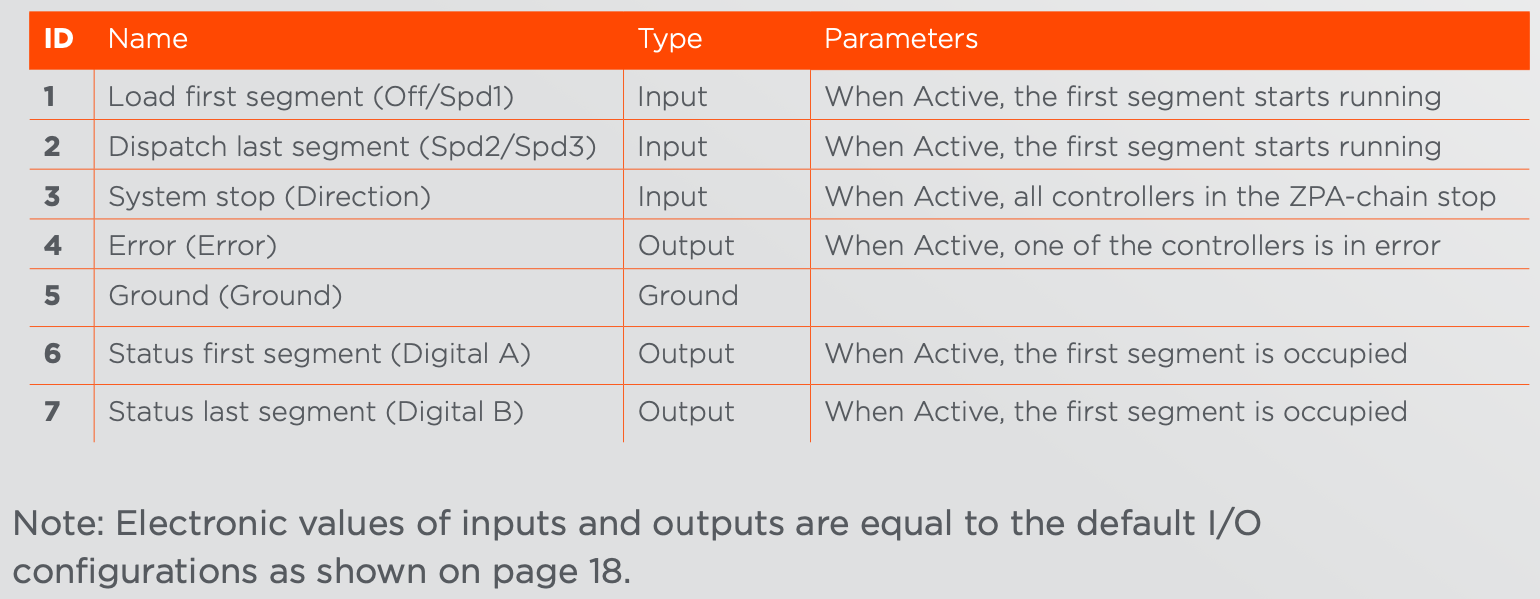
In order to achieve a System Stop, the first or last segment of the chain must be connected to an I/O device as described above. As shown in the I/O table on the next page, when input ID3 - System Stop is activated on the I/O device, all the controllers in the ZPA chain will come to an immediate stop. As soon as System Stop is deactived, the system will finish its task and continu operating.
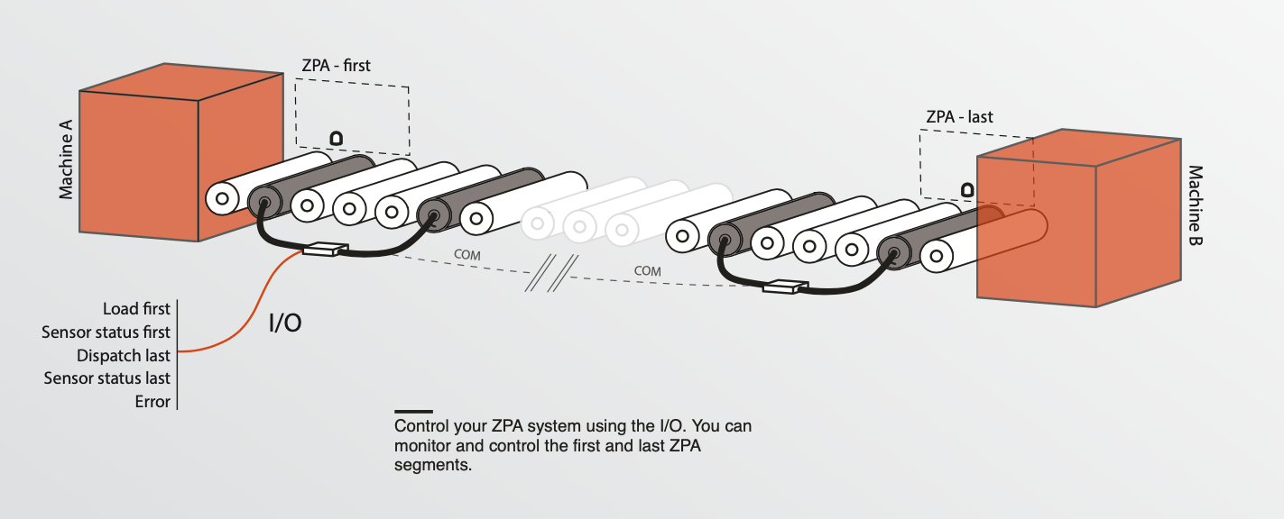
Setup of ZPA system
As mentioned before, in many applications it is required to have control over the first and last segment. In the figure below, an example of a typical ZPA application is shown, with an external machine/system at the beginning and end of the chain. If the settings are correctly configured as stated before, one can activate the first and last segment and read their status (free or occupied with package) via I/O to a PLC or similar device. In order to control the first and last segment, the function of the I/O pins is different from normal operation. An overview of these I/O pins is shown in the table below.
In many applications it is desirable to interact with the autonomously accumulating BP120 controllers. For example, if one would like to transport a product to the first segment of the ZPA chain, you must be able to communicate to this segment to start loading a product. Whereas, for the last segment in the ZPA chain, you would like to control when this segment dispatches a product downstream.
Configuration of settings in BP120
It is possible to interact and communicate with the first and last segment of the ZPA chain via external I/O. To communicate via I/O with the first and/or last segment, two settings in the UI must be set:
(1) the first and/or last segment must be set to I/O-mode. (Make sure only one side of the BP120 controller is set to I/O-mode since the other side of the controller is still communicating with the rest of the ZPA chain in COM-mode).
(2) Endpoint setting must be set to ZPA-first for the first segment and ZPA-last for the last segment. This can be done in the accumulation menu (ACC).
(Again, make sure only one side of the BP120 controller is set to ZPA-first or ZPA- last. The other side is just a default segment in the ZPA chain with the endpoint setting to “NO”.
If above settings are set, you are ready to interact with the ZPA system. In the upcoming sections, the different types of I/O interactions with the system are explained.
Emergency stop of ZPA system
It is possible to stop the autonomously working ZPA system in case of an emergency without cutting the complete power of the system.
In order to achieve a System Stop, the first or last segment of the chain must be connected to an I/O device as described above. As shown in the I/O table on the next page, when input ID3 - System Stop is activated on the I/O device, all the controllers in the ZPA chain will come to an immediate stop. As soon as System Stop is deactived, the system will finish its task and continu operating.
Setup of ZPA system
As mentioned before, in many applications it is required to have control over the first and last segment. In the figure below, an example of a typical ZPA application is shown, with an external machine/system at the beginning and end of the chain. If the settings are correctly configured as stated before, one can activate the first and last segment and read their status (free or occupied with package) via I/O to a PLC or similar device. In order to control the first and last segment, the function of the I/O pins is different from normal operation. An overview of these I/O pins is shown in the table below.